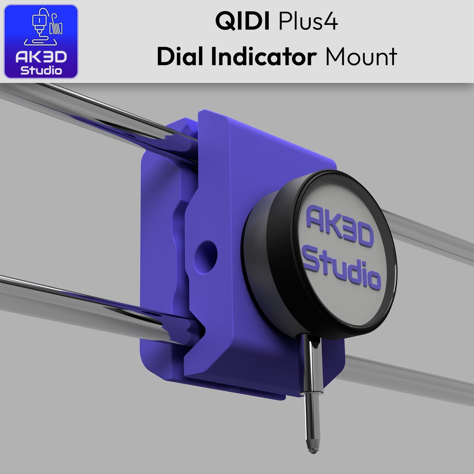
QIDI Plus4 Dial Indicator Mount – Free STL Files
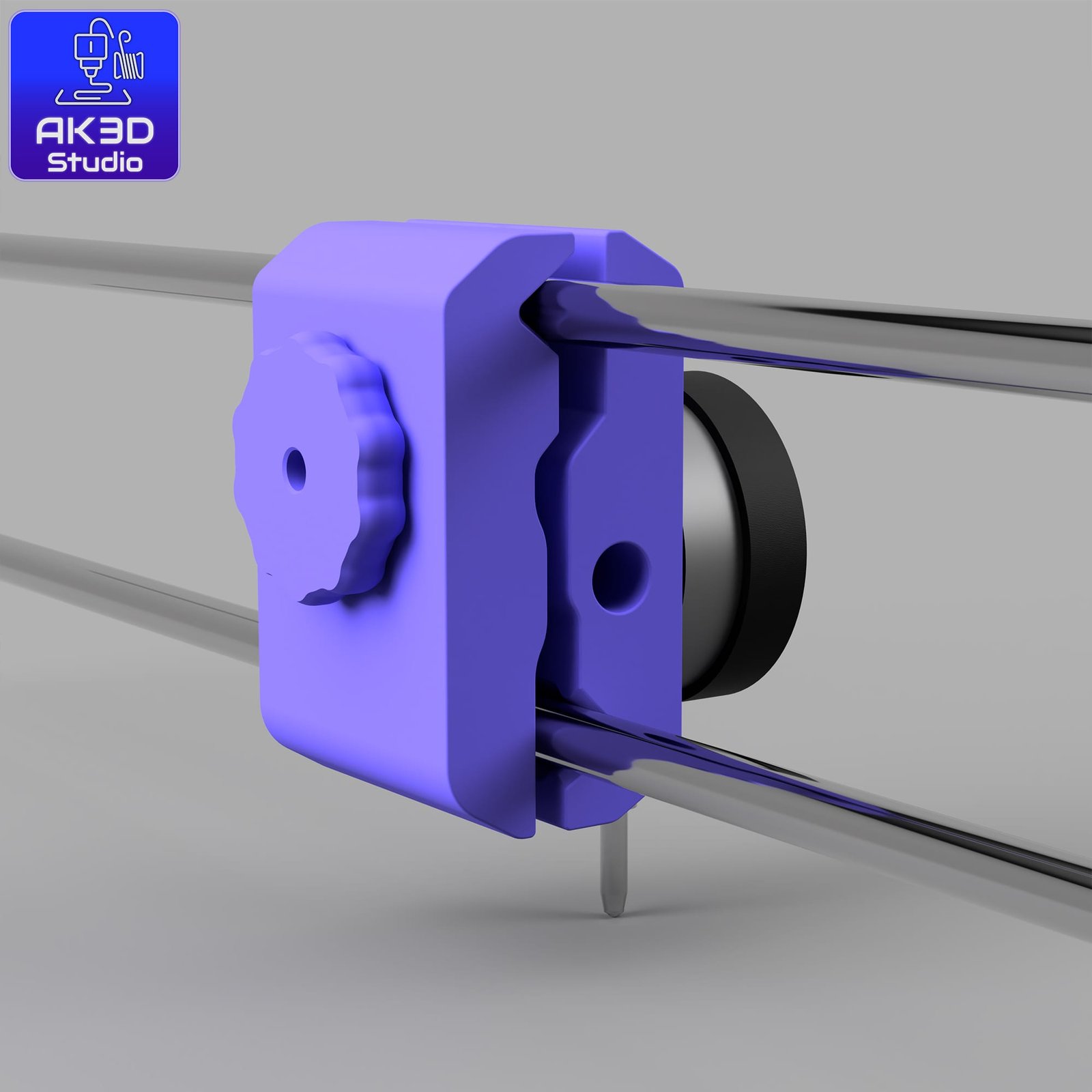
Here’s a simple mount I designed for the QIDI Plus4 to make bed levelling with a dial indicator easier and more consistent.
Thought I’d share the files so anyone can print their own.
What’s Included
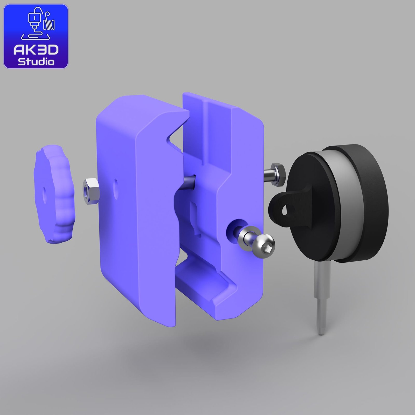
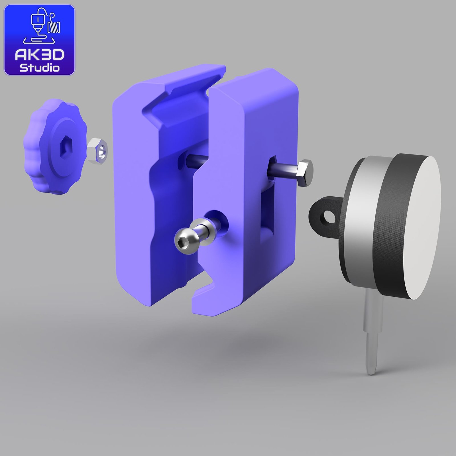
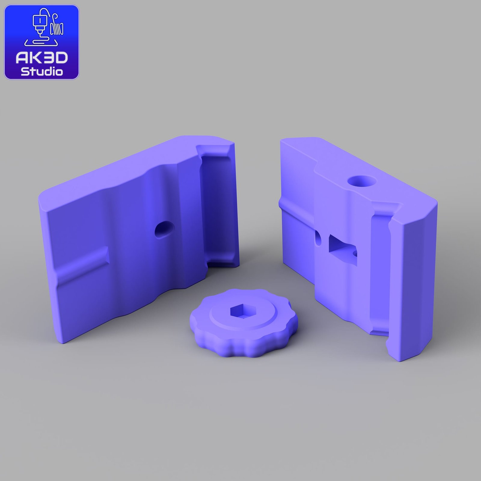
3 STL files (3 printed parts)
Hardware list with links for reference
Dial indicator options (different budgets, pick what works best for you)
Hardware You’ll Need
1x M6 x 50mm hex head bolt. (Like these: https://amzn.to/4mQ3IdI )
1x M6 nut
1x M6 washer
1x M6 cap head or button head screw (20-30mm) Something like this: Amazon Link
1x Dial indicator (same mounting point across brands)
👉 Some examples:
Mitutoyo 2044A – Amazon Link
Starrett 3025-481 – Amazon Link
Budget Option – Amazon Link
Print Settings (What I Used)
Material: ABS (recommended if you’ll be adjusting while the chamber is hot / bed at 100°C)
Layer height: 0.25mm worked fine for me
Supports: Not required
Notes
The mount was designed around the Mitutoyo I own, but other indicators with the same mounting point should fit too.
If you tweak the design or make improvements, I’d love to see your version!
Quick Manual – Level the Bed Parallel to the XY Gantry
This dial indicator mount helps you tram the bed so it’s parallel to the gantry. The goal is to get the same reading at points around the bed.
Before you start
Preheat the bed to your usual printing temp (e.g., 100 °C for ABS) and let it soak a few minutes.
Clean the surface you print on and use the same build plate you normally use.
If your printer/slicer uses any mesh/auto compensation, temporarily disable it for this process.
Setup
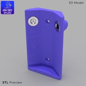
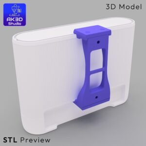
Mount the indicator to the print head using the printed parts.
Jog the head so the indicator tip sits on the bed near the front-left screw area.
Lower Z slowly until the plunger just touches, then compress ~1 mm more.
Zero the indicator. From now on, don’t reset zero until you’re done.
Leveling cycle
Left side first: Measure front-left, adjust that corner to read zero. Move to rear-left, adjust to zero.
Now the right side: Move to front-right, adjust to zero. Then rear-right, adjust to zero.
Repeat left ↔ right cycles. Each tweak can affect the others; do a couple of passes until all four read zero (or as close as you can get).
Notes & tips
I designed the mount around a Mitutoyo 2044A, but most dial indicators with the same mounting points should fit fine.
Move slowly in Z to avoid bottoming-out the plunger.
After tramming, re-enable any mesh compensation if you normally use it, and re-confirm your Z-offset with a quick first-layer test.
If you want a full step-by-step with photos/video, give me a shout – if there’s interest I’ll write a blog post with the whole process.
(And yep, this is free. If it helped and you’d like to support more projects like this, here’s an optional PayPal “buy me a coffee” link – totally up to you.)
📩 Got Questions? Feel free to [Contact Us] anytime!


Reviews
There are no reviews yet.